Persistent ID’s
Persistent ID’s are unique identifiers, either in the form of strings or integers, assigned to entities. However, not all entities have persistent ID’s as this depends on the file format.
HOOPS Exchange supports persistent ID’s for certain file formats, and you can see a full list of which ones in the indexed section below. Persistent ID’s are crucial for developers drawing data from multiple CAD systems, as they ensure that model entity ID’s remain consistent across different sessions.
Persistent IDs are stored as a field in the A3DRootBaseData structure, either as a string (A3DRootBaseData.m_pcPersistentId) or an integer (A3DRootBaseData.m_uiPersistentId).
This attribute can be accessed from the root base data. Additionally, for assembly members, the persistent ID can be retrieved using the A3DAsmProductOccurrenceGetIdentifier() function.
The persistent ID assigned to an entity is determined by the CAD format. When using HOOPS Exchange, you must ensure that each instance of reading the same file — or any version of it — is used. This guarantees that each entity is assigned the same identifiers as previously defined for the file. This consistency also ensures that entities with matching persistent IDs across different files can reliably be recognized as the same.
It is important to note that these ID’s are not guaranteed to be unique. In some cases, entities such as faces may share the same ID. This can occur, for example, when a feature like a groove is used to define a body. More specific examples of this scenario can be found in the tables located on the individual format pages listed in the index below. For detailed information, refer to the page links for Inventor, CATIA, or SolidWorks under their respective sections titled “Splitting a Face – Adding a Groove”.
Supported Formats and Modification Supports
Below is an index of the supported file formats, along with information on how different modifications to a part can impact their persistent ID’s. Select a format from the list to view detailed information specific to that file type.
Immutable Persistent ID Instances: Assembly Cases
There are also several instances where the persistent ID’s should never change. Read through the instances below for more information and examples.
Base Assembly
Persistent ID’s should never change during base assembly.
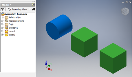
For example, notice in the image that several previously created CAD parts are being assembled to form a completed CAD product. Any manipulation of parts or objects during the assembly should never cause any change to a previously defined identifier.

Changing Order of Components
Persistent ID’s should never change if and when you change the order of components in an assembly model tree.
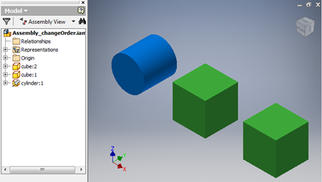
In the images provided below, we see a CAD assembly file that consists of several CAD parts.
Originally, the model tree reads the chronological order of cylinder 1, cube 1, and finally cube 2, as seen in the Original Order of Components image on the left. Note, in the Modified Order of Components image, the changes to the order of components in the model tree structure. Instead, we now see that the model tree structure lists the parts chronologically - as cube 2, cube 1, and then cylinder 1.
Despite these changes in the model tree parts structure, the persistent ID’s of any entities in any of the parts should remain the same.
| Original Order of Components | Modified Order of Components |
|---|---|

|

|
Editing Component Parameters
Persistent ID’s should never change if and when you edit any component parameters from within an assembly file.
In the images provided below, we see a CAD assembly file that consists of several CAD parts.
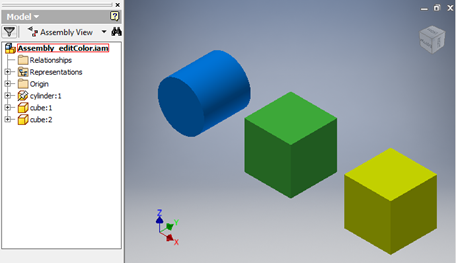
Originally, the model tree reads the chronological order of the components - cylinder 1, cube 1, and cube 2 - as seen in the Original Components in Assembly image on the left. In this image, note that the cylinder is blue, and the two cubes are green.
Conversely, note the colors of the 3 components in the image on the right, underneath Modified Component Parameters of Cube 2 in Assembly. Notice that the component parameters of cube 2 regarding color has been altered. Rather than green, cube 2 is now yellow.
Despite editing the component parameters of cube 2, the persistent ID’s of any entities in any of the parts should remain the same.
| Original Components Parameters of Assembly Parts | Modified Component Parameters of Cube 2 in Assembly |
|---|---|

|

|
Removing Components
Persistent ID’s should never change if and when you remove any components from an assembly file
In the images provided below, we see a CAD assembly file that consists of several CAD parts.
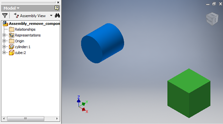
Originally, the model tree reads the chronological order of cylinder 1, cube 1, and finally cube 2, as seen in the original Components in Assembly image on the left. Note, in the Components in Assembly After Cube 1 Removal image, the removal of cube 1 from the assembly file in the model tree structure. Instead, it now chronologically lists 2 components in the model tree structure - cylinder 1 and cube 2.
Despite the removal of a component from the assembly file, the persistent ID’s of any entities in any of the parts should remain the same.
| Original Components in Assembly | Components in Assembly after Cube 1 Removal |
|---|---|

|

|
Additional Information
| File Type | Assembly Nodes | Solids | Faces | Edges | Density |
|---|---|---|---|---|---|
| CATIA V5 | Persistent ID string (CLSID) | Persistent ID integer (key) | Persistent ID string as attribute (string) | Persistent ID string as attribute | In ProductInformation (for each occurrence corresponding to a file) |
| Creo/Pro-E | Persistent ID string (CLSID) | Not applicable | Persistent ID integer (key) - Note: Persistent ID inside a part are different even when there are several solids. | Persistent ID integer (key) - Note: Persistent ID inside a part are different even when there are several solids. | Latest versions of Creo have them. Otherwise, we put the stored filename. |
| NX | Persistent ID string (CLSID) | Persistent ID integer (key) | Persistent ID integer (key) | Persistent ID integer (key) | In ProductInformation (for each occurrence corresponding to a file) |
| SolidWorks | Persistent ID string (CLSID) | Persistent ID integer (key) | Not applicable | Not implemented | In ProductInformation (for each occurrence corresponding to a file) |
| SolidEdge | Persistent ID string (CLSID) | Persistent ID integer (key) | Persistent ID string as an attribute | Not implemented | In ProductInformation (for each occurrence corresponding to a file) |
| Inventor | Persistent ID string (CLSID) | Persistent ID integer (key) | Persistent ID string as an attribute | Not implemented | In ProductInformation (for each occurrence corresponding to a file) |

