Geometry Handles
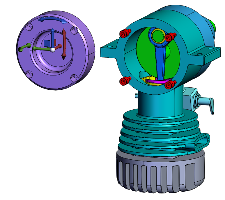
After you read this guide, you should know how to add handles to the scene and customize the handle geometry.
Introduction
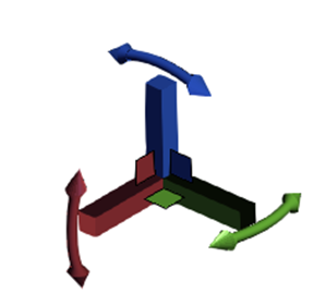
Geometry handles are used to change the position matrix of parts in the scene. There are two types of transformation: translation and rotation. The handle operator adds ten default handles; three axis translation, four plane translation, and three axis rotation. One plane translation handle translates along the plane defined by the view plane normal. All other handles rotate or translate around the X, Y, or Z axis.
The handle operator is used to interact with the handles in the scene. It listens for handle events and transforms parts accordingly. It also provides an API for interfacing with the handles. The API can be used for adding handles at a position, setting which nodes are moved by the handles, transforming world space points as the handles are moved, setting the handle size scalar, adding handles oriented along an arbitrary vector, and customizing the geometry that is displayed for the handles.
Handle operator
Get the handle operator
const handleOperator = hwv.operatorManager.getOperator(Communicator.OperatorId.Handle);
Handle placement position
The following code assumes that a face has been selected. For brevity, we will omit checking for a null selection item.
    const selectionItem = hwv.selectionManager.getFirst();
    const nodeId = selectionItem.getNodeId();
    const position = selectionItem.getPosition();
    const normal = selectionItem.getFaceEntity().getNormal();
To position the handles at the center of the bounding box for the selected parts, we can use the addHandles() function, and provide an array of node IDs.
handleOperator.addHandles([nodeId]);
To position the handles at a world space coordinate, the add handles function can be used with the optional position parameter added. If a position is explicitly provided, the node ids can optionally be added with the setNodeIds() function.
handleOperator.addHandles([], position);
Set node IDs
To set the node ids for the parts that will be moved with the handles, use the setNodeIds() function.
handleOperator.setNodeIds([nodeId])
Point tracking
The handle operator allows world space points to be tracked and updates the position as the handles move. This can be useful if you have line markup that is attached to a position on a part. When the handles are used to move a part, you can easily keep track of the new point position, and update the line markup.
const index = handleOperator.addTrackedPoint(position);
The index of the tracked point returned from the addTrackedPoint() function can be used to retrieve the new position in the array of points returned by the getTrackedPoints() function. The getTrackedPoints() function can be called after receiving a handle event to keep any markup
const newPosition = handleOperator.getTrackedPoints()[index];
Handle scale
To change the handle scale, use the setHandleSize() function. This must be set before the handles are added to the scene.
handleOperator.setHandleSize(2);
Custom handle configuration
Instead of using the default handle configuration, you can add your own set of handles to the scene. For example, if you want to move along the X and Y axis only, you can add just the X axis, Y axis, and Z plane handles.
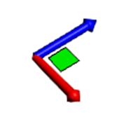
    handleOperator.addAxisTranslationHandle(position, new Communicator.Point3(1, 0, 0), Communicator.Color.red());
    handleOperator.addAxisTranslationHandle(position, new Communicator.Point3(0, 1, 0), Communicator.Color.blue());
    handleOperator.addPlaneTranslationHandle(position, new Communicator.Point3(0, 0, 1), Communicator.Color.green(), Communicator.Color.black(), new Communicator.Point3(-1,0,0));
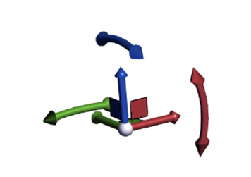
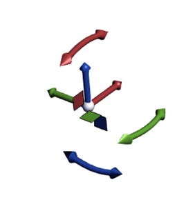
NOTE: Notice the last parameter in addPlaneTranslationHandle, new Communicator.Point3(-1,0,0)). This is a position vector that can control the orientation of the handle. Since the axis handles are symmetrical and are drawn along the axis, there is no need to specify a position vector. The rotate handles and plane translation handles however, require a position vector to place them in the default orientation. The pictures below show the default handles with and without the position vector. For the X, Y and Z axis, the position vector used in the default configuration is inverse Y, inverse Z, and inverse X respectively.
Custom handle geometry
The geometry that gets used by default for the axis, plane, view plane, and rotate handles can be set using the following functions:
- setAxisMeshData()
- setPlaneMeshData()
- setViewPlaneMeshData()
- setRotateMeshData()
Each function takes a MeshData object that represents the geometry for the X axis. The geometry will be transformed to match the normal that will be used to apply the transformation when the handles are added.
The following code replaces the axis cylindrical handles with a rectangle.
    const length = 10;
    const width = 1;

    const axisX = new Communicator.Point3(1, 0, 0);
    const axisY = new Communicator.Point3(0, 1, 0);
    const axisZ = new Communicator.Point3(0, 0, 1);
    const invAxisX = new Communicator.Point3(-1, 0, 0);
    const invAxisY = new Communicator.Point3(0, -1, 0);
    const invAxisZ = new Communicator.Point3(0, 0, -1);

    const p1 = new Communicator.Point3(-width, width, width);
    const p2 = new Communicator.Point3(-width, length, width);
    const p3 = new Communicator.Point3(width, length, width);
    const p4 = new Communicator.Point3(width, width, width);
    const p5 = new Communicator.Point3(-width, width, -width);
    const p6 = new Communicator.Point3(-width, length, -width);
    const p7 = new Communicator.Point3(width, length, -width);
    const p8 = new Communicator.Point3(width, width, -width);

    const axisFaces = [
        p1, p2, p3,
        p3, p4, p1,

        p6, p5, p8,
        p8, p7, p6,

        p1, p5, p6,
        p6, p2, p1,

        p4, p3, p7,
        p7, p8, p4,

        p5, p1, p4,
        p4, p8, p5,

        p2, p6, p7,
        p7, p3, p2,
    ];

    const axisNormals = [
        axisZ,
        invAxisZ,
        axisY,
        invAxisY,
        axisX,
        invAxisX,
    ];

    const faceData = [];
    axisFaces.forEach((p: Communicator.Point3) => {
        faceData.push(p.x);
        faceData.push(p.y);
        faceData.push(p.z);
    });

    const normalData = [];
    axisNormals.forEach((p: Communicator.Point3) => {
        for (let i = 0; i < 6; ++i) {
            normalData.push(p.x);
            normalData.push(p.y);
            normalData.push(p.z);
        }
    });

    const axisMeshData = new Communicator.MeshData();
    axisMeshData.addFaces(faceData, normalData);
    axisMeshData.setFaceWinding(Communicator.FaceWinding.Clockwise);

    handleOperator.setAxisMeshData(axisMeshData);
Custom handle axis
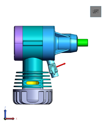
handleOperator.addAxisTranslationHandle(position, normal, Communicator.Color.red());
Handle events
The following callbacks contain information about drag events as they occur. This includes the type of handle event (translate vs rotate), the node ids for the parts that are transformed, and the matrices for those nodes (initial matrix for handleEventStart, initial and new matrix for handleEvent and handleEventEnd)
handleEventStart– triggered when the handle operator begins to drag the handles.handleEvent– triggered on each drag update.handleEventEnd– triggered when the drag event has finished.
    hwv.setCallbacks({
        handleEventStart: (eventType: Communicator.HandleEventType, nodeIds: Communicator.NodeId[], initialMatrices: Communicator.Matrix[]) => {
            //handle event started
        },
        handleEvent: (eventType: Communicator.HandleEventType, nodeIds: Communicator.NodeId[], initialMatrices: Communicator.Matrix[], newMatrices: Communicator.Matrix[]) => {
            //handle dragged
        },
        handleEventEnd: (eventType: Communicator.HandleEventType, nodeIds: Communicator.NodeId[], initialMatrices: Communicator.Matrix[], newMatrices: Communicator.Matrix[]) => {
            //handle event finished
        }
    });

