UnstructGrid: Create an Isovolume

An isovolume is defined as the combined volume of the element model where the scalar field is between a given minimum and maximum value. The surface of the isovolume will be the hull of this volume. Any element on the border of the model (a surface with no neighbor) is also included in the volume if if the value of that surface is in the given range.
Isovolumes may be computed from any scalar result. In addition, another scalar result can be mapped as fringes onto the isovolume, showing for instance the variation of temperature over a volume of of a given min and max pressure.
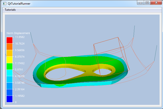
This tutorial shows how to create an isovolume based on a scalar result id and a maximum and minimum scalar value. In addition, the scalar result will be shown as fringes on the isosurface.
The demo file (contact.vtfx) contains a geometry with four parts. This tutorial will use the displacement result to define the isosurface.
Load the file and setup the model specification to show the result. For a more thorough explanation on creating a data source from a file interface and setup the model specification, see the Load VFTx tutorial: UnstructGrid: Load Model from File and Set Up Model Specification
Note
This tutorial expect the application to have a correctly configured cee::vis::View
in place. See demo applications on how to set up a cee::vis::View in your application.
Load model
Create the model and a VTFx file interface data source. Open the file and set the created data source in the model.
    cee::PtrRef<cee::ug::UnstructGridModel> ugModel = new cee::ug::UnstructGridModel();
    cee::PtrRef<cee::ug::DataSourceVTFx> source = new cee::ug::DataSourceVTFx(42);

    cee::Str vtfxFile = TutorialUtils::testDataDir() + "contact.vtfx";
    if (!source->open(vtfxFile, 0))
    {
        // VTFx file not found
        return;
    }

    ugModel->setDataSource(source.get());
Set the fourth state as current in the model specification. (The displacement is zero in the first state.)
    std::vector<cee::ug::StateInfo> stateInfos = source->directory()->stateInfos();
    int stateId = stateInfos[3].id();
    ugModel->modelSpec().setStateId(stateId);
Create the isovolume
The isovolume is defined by a scalar result id and a minimum and a maximum scalar value.
Create the isovolume object. Remember that the object is reference counted and should not be created on the stack.
    cee::PtrRef<cee::ug::Isovolume> isoVolume = new cee::ug::Isovolume();

    std::vector<cee::ug::ResultInfo> resultInfos = source->directory()->scalarResultInfos();
    int scalarId = resultInfos[0].id();
    isoVolume->setIsoScalarResultId(scalarId);
    isoVolume->setMinimumIsoValue(5.5);
    isoVolume->setMaximumIsoValue(7.5);
Set the scalar result to be shown as mapped fringes on the isovolume surface.
isoVolume->setMapScalarResultId(scalarId);
Add the isovolume to the model.
ugModel->addIsovolume(isoVolume.get());
To get a better view of the cutting plane inside the model, set all normal parts draw style to LINES.
    cee::ug::PartSettingsIterator it(ugModel.get());
    while (it.hasNext())
    {
        cee::ug::PartSettings* partSettings = it.next();
        partSettings->setDrawStyle(cee::ug::PartSettings::OUTLINE);
    }
Set up the created model
The model is ready to use and can be added to the view. Exactly where the view exists
depends on the platform and solution. These examples uses Qt and the view is set up
in a cee::qt::ViewerWidget.
    cee::vis::View* gcView = getTutorialView();
    gcView->addModel(ugModel.get());
See the complete source code here:
