UnstructGrid: Using DataElementSets to Filter the Model
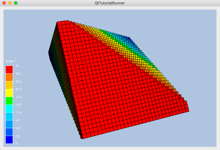
This tutorial shows how to create element sets and how to use the filtering to control which elements to show.

void TutorialRunnerMainWindow::addDataElementSets()
{
    //--------------------------------------------------------------------------
    // Load an UnstructGridModel from file
    // Create two sets and use them to filter the model
    //--------------------------------------------------------------------------

    // Create the model and data source
    cee::PtrRef<cee::ug::UnstructGridModel> ugModel = new cee::ug::UnstructGridModel();
    cee::PtrRef<cee::ug::DataSourceVTF> source = new cee::ug::DataSourceVTF(42);

    // Open the vtf file
    cee::Str vtfFile = TutorialUtils::testDataDir() + "30x30x30.vtf";
    if (!source->open(vtfFile))
    {
        return;
    }

    // Add the data source to the model
    ugModel->setDataSource(source.get());

    // Set the first state as current
    std::vector<cee::ug::StateInfo> stateInfos = source->directory()->stateInfos();
    int stateId = stateInfos[0].id();
    ugModel->modelSpec().setStateId(stateId);

    // Get the id of the scalar result and show it as fringes
    std::vector<cee::ug::ResultInfo> scalarResultInfos = source->directory()->scalarResultInfos();
    int scalarId = scalarResultInfos[0].id();
    ugModel->modelSpec().setFringesResultId(scalarId);

    // We need to update the visualization before we can generate any sets
    ugModel->updateVisualization();

    // Create one set with all items above the first plane
    cee::ug::DataElementSetGenerator setGenerator(*ugModel, 0);
    cee::Plane plane1 = cee::Plane::createFromPointAndNormal(cee::Vec3d(10,10,10), cee::Vec3d(1, 1, 1));
    cee::PtrRef<cee::ug::DataElementSet> set1 = setGenerator.createFromPlane(1, plane1, cee::ug::DataElementSetGenerator::FRONT | cee::ug::DataElementSetGenerator::ON);

    // Create one set with all items below the second plane
    cee::Plane plane2 = cee::Plane::createFromPointAndNormal(cee::Vec3d(20,20,20), cee::Vec3d(1, 1, 1));
    cee::PtrRef<cee::ug::DataElementSet> set2 = setGenerator.createFromPlane(2, plane2, cee::ug::DataElementSetGenerator::BACK | cee::ug::DataElementSetGenerator::ON);

    // Create the intersection between set1 and set2 in order to get a set with the elements in both sets, i.e. between the planes
    set1->intersect(*set2);

    // Add the main set to the data source so we can use it for filtering
    ugModel->dataSource()->addElementSet(set1.get());

    // Set the sets as our visible sets
    ugModel->modelSpec().setVisibleSetId(1);

    // Show surface with the element mesh
    cee::ug::PartSettingsIterator it(ugModel.get());
    while (it.hasNext())
    {
        cee::ug::PartSettings* partSettings = it.next();
        partSettings->setDrawStyle(cee::ug::PartSettings::SURFACE_MESH);
    }

    // Add model to view. Ensure that old models are removed first
    cee::vis::View* view = getTutorialView();
    view->removeAllModels();
    view->addModel(ugModel.get());

    ugModel->updateVisualization();

    cee::BoundingBox bb = view->boundingBox();
    view->camera().fitView(bb, cee::Vec3d(0, 0, -1), cee::Vec3d(0, 1, 0));
    view->camera().inputHandler()->setRotationPoint(bb.center());

    view->requestRedraw();
}
