cee::ug::CuttingPlane
-
class CuttingPlane : public RefCountedObject
Configuration of a cutting plane.
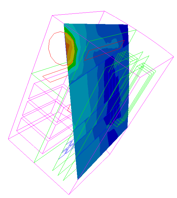
Cutting planes are slices through the structure onto which scalar and vector fields can be visualized. By dynamically changing the position and orientation of the cutting plane, you can quickly analyze the results inside the system.
Cutting planes are available for unstructured grid models.

See the topic: Cutting Planes
See tutorial: UnstructGrid: Create a Cutting Plane with a Scalar Result as Fringes
A cutting plane is defined by a point and a normal vector. Any number of cutting planes can be defined and displayed, and various display attributes can be set separately for each cutting plane.
As for normal parts, cutting planes can also toggle visibility and be highlighted.
Cutting planes has some simple part settings for the visualized cutting plane surface, for example:
Show plane surface on/off
Show mesh on/off
Surface fixed color
Draw style
Opacity
Onto each cutting plane, a mapped scalar, contour lines and a vector result can be visualized.
Fringes
Show scalar fringes on a cutting plane using
setMapScalarResultId() with the requested scalar result id.Contour lines
Show scalar as contour lines on a cutting plane using
setMapContourLinesResultId() with the requested scalar result id.Vectors
Show a vector result mapped on the cutting plane using
setMapVectorResultId() with the requested vector result id. The vector arrows will be positioned in a grid pattern. Tune the vector result presentation by adjusting the grid spacing with setVectorGridSpacing().
Note! Remember that this object is reference counted and should never be created on the stack.

Clipping
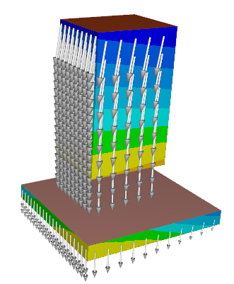
Cutting planes can also be used to clip the model in the same plane as the cutting plane. In the image to the right two cutting planes are defined with clipping enabled on both planes. Only the part of the model on the correct side of both cutting planes will be visible. Vectors and the cutting plane itself are clipped accordingly.

Bounded clipping planes
Model settings has a setting setMustBeBehindAllCuttingPlanesToClip where you can control how clipping against cutting planes will be done if more than one plane is specified.
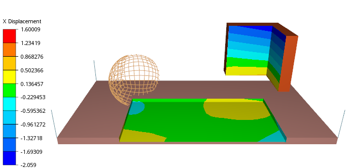
Useful for creating “bounded clipping planes” where you define multiple planes in a way that only fragments rejected by all (e.g. inside a box) will be rejected. This allows for “cutting into” a model without removing everything one one side of a plane.
The default value is 1, which is normal clipping and a fragment is clipped if clipped by one (or more) clipping planes (as seen in the example above).
To the right there is an example of a Model with 4 clipping plane defining the bottom, right, back, and left cutting plane with clipping enabled. setMustBeBehindAllCuttingPlanesToClip(true) is used to create bounded clipping planes.
Example
This example shown how to create a cutting plane with scalar result mapped on the surface.
Find the id of the first scalar result from the data source’s directory.
std::vector<cee::ug::ResultInfo> scalarResultInfos = source->directory()->scalarResultInfos();
int scalarId = scalarResultInfos[0].id();
Create the cutting plane object. Remember that the object is reference counted and should not be created on the stack.
The cutting plane is defined by a point in the plane and the normal to the plane.
cee::PtrRef<cee::ug::CuttingPlane> cuttingPlane = new cee::ug::CuttingPlane();
cuttingPlane->setPoint(cee::Vec3d(10, 10, 10));
cuttingPlane->setNormal(cee::Vec3d(1, 1, 1));
Set the scalar result to be shown as mapped fringes on the cutting plane surface.
cuttingPlane->setMapScalarResultId(scalarId);
Add the cutting plane to the model.
ugModel->addCuttingPlane(cuttingPlane.get());
To get a better view of the cutting plane inside the model, set all parts to transparent.
cee::ug::PartSettingsIterator it(ugModel.get());
while (it.hasNext())
{
    cee::ug::PartSettings* partSettings = it.next();
    partSettings->setOpacity(0.5f);
}
See the complete source code at: UnstructGrid: Create a Cutting Plane with a Scalar Result as Fringes
Tutorials: See tutorial: UnstructGrid: Create a Cutting Plane with a Scalar Result as Fringes
See also
Public Types
Public Functions
-
CuttingPlane()
Constructs an empty cutting plane.
-
bool visible() const
Returns true if the cutting plane is visible.
-
void setVisible(bool visible)
Toggles cutting plane visibility.
-
bool highlight() const
Returns true if the cutting plane is highlighted.
-
void setHighlight(bool showHighlighted)
Specifies if the cutting plane is shown highlighted or not.
-
float eyeLiftFactor() const
Returns the eye lift factor of the cutting plane.
See also
-
void setEyeLiftFactor(float factor)
Sets the eye lift factor for the cutting plane.
The eye lift factor specifies if the cutting plane should be moved towards the camera (or away from the camera if the factor is negative).
This is useful for controlling the ordering of items that are defined in the same plane.
Note
Does not affect the clipping plane in any way.
-
bool lighting() const
Returns true if the cutting plane is rendered with lighting.
-
void setLighting(bool enable)
Enables or disables lighting of the cutting plane.
-
bool planeSurfaceVisible() const
Returns true if cutting plane surface is visible.
-
void setPlaneSurfaceVisible(bool show)
Specifies if the cutting plane surface is visible or not.
-
float opacity() const
Returns the opacity of the cutting plane.
1.0 is opaque and 0.0 is fully transparent (invisible)
-
void setOpacity(float opacity)
Sets the opacity of the cutting plane.
1.0 is opaque and 0.0 is fully transparent (invisible)
-
float specularIntensity() const
Returns the specular intensity set for this cutting plane.
-
void setSpecularIntensity(float intensity)
Sets the specular intensity to use for this cutting plane.
The specular intensity control the highlight and reflection of the light onto the part. The light is white, so this will cause the color of the part to get more white in the parts that reflect the light source.
Default is 0.5. Legal range is 0.0 -> 1.0, where 0.0 turns off the specular highlight.
-
bool useSourcePartColor() const
Returns true if the color of the source part of the cutting plane will be used as the plan color (if no results are shown).
-
void setUseSourcePartColor(bool useSourcePartColor)
Specifies to use the color of the source part or a fixed color for the cutting plane.
-
bool crinkleCutSurface() const
Returns true if the cutting plane is showing a crinkle cut surface.
See also
-
void setCrinkleCutSurface(bool useCrinkleCutSurface)
Specifies if the cutting plane should show a crinkle cut surface.
If enabled, the cutting plane surface will be the combined surface of all elements intersected by the cutting plane. So the cutting plane will show the tessellation of all intersected elements.
This is useful for inspecting and visualizing the mesh of a volume element model.
-
bool clipping() const
Returns true if clipping of the model by the cutting plane is enabled.
-
void setClipping(bool enableClipping)
Enables clipping of the model by the cutting plane.
This will create a clipping plane in the same position as the cutting plane with will clip the model (and any other clipping planes or isosurfaces).
-
void setPoint(Vec3d pointInPlane)
Sets a point that the cutting plane passes through.
A cutting plane is defined by a point and a normal vector.
See also
-
void setNormal(Vec3d normal)
Sets the cutting plane’s normal vector.
A cutting plane is defined by a point and a normal vector.
See also
-
bool computeFromVisibleParts() const
Returns true if cutting plane applies to visible parts only.
-
void setComputeFromVisibleParts(bool visiblePartsOnly)
Sets the cutting plane to only cut visible parts.
-
bool alsoComputeFromUndeformedModel() const
Returns true if cutting plane applies to visible parts only.
-
void setAlsoComputeFromUndeformedModel(bool alsoShowForUndeformedModel)
Sets the cutting plane to only cut visible parts.
-
int mapScalarResultId() const
Returns the id for the current scalar result mapped on the cutting plane.
Returns -1 if none.
-
void setMapScalarResultId(int resultId)
Sets scalar result to map onto the cutting plane surface.
The selected scalar result is shown as fringes. Set resultId to -1 to clear the mapped scalar result.
-
int mapVectorResultId() const
Returns the id of the current vector result shown on the cutting plane.
Returns -1 if none.
-
void setMapVectorResultId(int resultId)
Sets vector result to show on the cutting plane surface.
Vector arrows are shown along computed grid lines. To change the default grid spacing with setVectorGridSpacing() Set resultId to -1 to clear the mapped vector result.
See also
-
int mapContourLinesResultId() const
Returns the id of the contour lines result currently mapped on the cutting plane.
Returns -1 if none.
-
void setMapContourLinesResultId(int resultId)
Sets the contour lines result to be mapped on the cutting plane.
Set resultId to -1 to clear the mapped contour lines result.
-
double vectorGridSpacing() const
Returns the grid spacing to use for the vectors on the cutting plane.
See also
-
SpacingMode vectorGridSpacingMode() const
Returns the current spacing mode used when mapping vectors onto the cutting plane.
See also
-
void setVectorGridSpacing(SpacingMode mode, double spacing)
Sets the grid spacing used for drawing vectors on cutting planes.
If mode is RELATIVE_SPACING, the value spacing is is interpreted as a fraction of the model extent. If mode is ABSOLUTE_SPACING, the specified spacing will be used regardless of the model extent. The default is a relative spacing of 0.025.
See also
-
bool gridLinesVisible() const
Returns true if grid lines are set visible on cutting plane.
-
void setGridLinesVisible(bool visible)
Sets grid line visibility.
-
bool projectVectorsOnPlane() const
Returns true if the vectors are projected onto the cutting plane.
-
void setProjectVectorsOnPlane(bool project)
Sets if the vectors should be projected onto the cutting plane or not.
-
bool isPrecomputed() const
Returns true if the cutting plane is precomputed.
Precomputed cutting plane cannot be altered or moved.
-
double sampleScalarValue(int stateId, const Vec3d &samplePosition, size_t triangleIndex = cee::UNDEFINED_SIZE_T) const
Returns the sampled scalar value at the given sample position for a specified state.
triangleIndex is optional and will speed up the lookup if provided. This corresponds to the cee::ug::HitItem::triangleIndex() value.
Returns cee::UNDEFINED_DOUBLE if no value was found.
-
Vec3d sampleVector(int stateId, const Vec3d &samplePosition, size_t triangleIndex = cee::UNDEFINED_SIZE_T) const
Returns the sampled vector value at the given sample position for a specified state.
triangleIndex is optional and will speed up the lookup if provided. This corresponds to the cee::ug::HitItem::triangleIndex() value.
Returns a Vec3d with x, y, and z set to cee::UNDEFINED_DOUBLE if no vector values was found.
-
void data(int stateId, CuttingPlaneData *cuttingPlaneData)
Gets the cutting plane data for the given state.
The cutting plane data contains raw triangle data and result values.
See also
-
void partData(int stateId, size_t globalGeometryIndex, int partId, CuttingPlaneData *cuttingPlaneData)
Gets the cutting plane data for the given state and part.
The cutting plane data contains raw triangle data and result values.
See also
-
void setPerFrameTransformationMatrices(const std::vector<Mat4d> &matrices)
Sets per frame transformation matrices for the cutting plane.
This is useful to a have a cutting plane that moves during an animation. E.g. slicing through the model or following an object in your model.
-
size_t transformationMatrixFrameCount() const
Returns the number of frames there are transformation matrices defined for.
