Data Model
Introduction
HOOPS Publish enables the creation of interactive documents featuring distinct data and view layers.
For example, data can be stored within a data table, which can later be bound to widgets such as a scroll table or a list box.
Moreover, the relationship between distinct data tables can define dynamic behavior within a PDF, updating the content displayed in a widget whenever a specific event (such as a mouse-click selection) occurs elsewhere in the document.
The subsequent sections provide a more detailed explanation of how this functionality operates.
Creating a Data Table
A Data Table is a tabular data structure that stores an array of pointers to strings of type A3DUTF8Char.
struct {
    A3DInt32      uNbRow;
    A3DInt32      uNbCol;
    A3DUTF8Char** m_ppcTexts;
} A3DPDFDataTableData;
It can be utilized to store content intended for display in various field or high-level widget types, such as text fields, list boxes, buttons, scroll tables, and more.
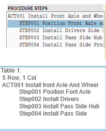
To display the following items in a list box, define a table with five rows:

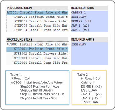
The content displayed in a particular widget can change depending on the selection made in another widget. In this example, the information shown in the “Required Parts” list box is updated based on the item selected in the “Procedure Steps” list box.

In this case, Table 2 is used to define all the content that could potentially be displayed in the “Required Parts” list box.
Setting a Relationship Between Tables
In the previous example, clicking on an item in the “Procedure Steps” widget dynamically populates the data in the “Required Parts” list box.
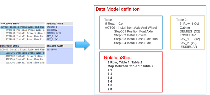
To define this, a relationship table must be established:
struct {
    A3DPDFDataTableData* pTable1;
    A3DPDFDataTableData* pTable2;
    A3DInt32             m_iSizeMap;
    A3DPDFMapIndexData*  m_pMapIndexes;
} A3DPDFDataRelationshipData;
This table will establish a relationship (a data mapping) between Table 1 and Table 2, specifying what content from Table 2 will be displayed whenever an item in Table 1 is selected:

Binding a Data Table
Once the data tables have been created, they need to be bound to widgets that are used to display their content. This is achieved using the BindToTable functionality, which can be applied to:
TextFieldScrollTableListBoxDropDownListViewCarouselDataFilter3DNodeScene3DViewList
Binding columns
The columns of the widgets need to be associated with columns of the bound data table.
This association is accomplished by providing a map of columns in the binding function call.
Specific columns can be designated in a data table to associate actions with the selection of a row. These columns are not displayed in the widget.
These action columns must be bound to the widgets using the A3DPDFWidgetBindColumnsActions() function.
Defining a Widget Behavior on Interaction
Finally, a behavior type must be defined to describe how widgets will be updated when an item is selected in another source widget.
In the following example, the data in the Required Parts listbox will be updated after a Procedure Step is selected.
| Isolated | Highlighted |
|---|---|
 |
 |
Three types of behavior can be defined: Isolate, Highlight and Select.
Setting the behavior is done by calling A3DPDFWidgetSetTargetBehaviour().
See the function description for more information.
The following example chooses the “Isolate” behavior:
A3DPDFWidgetSetTargetBehaviour(pListBox_ProcedureStep, pListBox_Requiredpart, kA3DPDFDataIsolate);
Setting up Properties for Highlight or Select on 3D Scene Widget
Some widgets have specific possibilities when they are set as targets. Particularly, the widget 3DNodeScene (which is a representation of 3D nodes via the 3D model tree or via the 3D annotation scene) commands the highlight or the selection of 3D nodes, and properties exist to set options for this. With this, customers can write some JavaScript at the document level (typically on the UI widgets on a page) to set the properties for highlight or select behaviours on the 3D scene. Also, some C API functions are available to set specific properties at initialization time.
Setting Properties at JavaScript level
To set the highlighting or selection properties on a 3D scene, customers must first get the javascript manager from the 3DNodeScene widget. Then some javascript code should be written to set properties on the manager object.
Getting JavaScript Manager
The HOOPS Publish function to get javascript manager is A3DPDF3DNodeSceneGetJavascriptHighlightManagerName().
Note for advanced developpers that might need to go deep in the code to handle specific requirements: following JavaScript functions are provided by HOOPS Publish at document level to get the manager object:
// to get manager by specifying the unique id of the 3D annotation:
getNodesManagerFor3DAnnotWithId(3dannotuniqueid)
// to get manager by specifying the page index and the index of annotation into this page.
getNodesManagerFor3DAnnot(pageIndex, annotIndex)  // to specify the page index and 3D annot index on the page
Setting Properties for Highlight on Manager JavaScript Object
Following properties are supported to control highlighting by using set methods on javascript manager object and accessible with the getHighlightProperties() function:
setHighlightColor(r,g,b): Highlight color in Red/Green/Blue component, each channel in [0.0;1.0] space. Default is red.setLevelOpacity(dLevelOpacity): Percentage of opacity applied in transparency mode, in [0.0;1.0] (defaults to 0.2).setBlinking(bBlinking): Iftruethe highlighted nodes are blinking.setBlinkNumber(iBlinkNumber): Number of times the nodes are blinking (default: 3).setBlinkPeriod(iBlinkPeriod): Duration of blink in ms (default: 300) .setHighlightMode(eHighlightMode): Set highlight modes with following values:_TS3D_HIGHLIGHTED_MESHES_MODE.ISOLATED_NOTCOLORED_OPACIFIED: the highlighted nodes are isolated, not colored, and opacified._TS3D_HIGHLIGHTED_MESHES_MODE.ISOLATED_COLORED_TRANSPARENT: the highlighted nodes are isolated, colored, and set transparent._TS3D_HIGHLIGHTED_MESHES_MODE.COLORED_OPACIFIED_OTHERSOPACIFIED: the highlighted nodes are colored and opacified, other nodes in the scene are opacified_TS3D_HIGHLIGHTED_MESHES_MODE.COLORED_OPACIFIED_OTHERSTRANSPARENTS: the highlighted nodes are colored and opacified, other nodes in the scene are set transparent_TS3D_HIGHLIGHTED_MESHES_MODE.COLORED_TRANSPARENT_OTHERSTRANSPARENTS: the highlighted nodes are colored and set transparent, other nodes in the scene are set transparent
Note that some of these modes are meaningful only when the highlighted entities are faces.
setZoomingToNodes(bZoomingToNodes): Iftrue, when the nodes are highlighted, the camera is zoomed to the highlighted nodes and the rotation center is moved to the center of the bounding box of these nodes.
An example of usage of this code is implemented in the DemoDataModel sample
Setting Properties for Select on Manager JavaScript Object
Following properties are supported to control selection by using set methods on javascript manager object and accessible with the getSelectProperties() function:
setZoomingToNodes(bZoomingToNodes): Iftrue, when a node is selected, the camera is zoomed to the selected node and the rotation center is moved to the center of the bounding box of this node.
Setting Zoom Property at C level
The specific property to set or unset the Zoom when the nodes are highlighted or selected can be set at a C level, which enables this property to be effective at initialization time, without any end-user UI.
To do this, customers can use the function A3DPDF3DNodeSceneSetZoomOnBehaviour(). The parameter A3DPDFEWidgetTargetBehaviour is to select the Highlight or Select behaviour on which to set the zoom property.
With kA3DPDFDataHighlight behaviour and zoom activation, when the nodes are highlighted, the camera is zoomed to the highlighted nodes and the rotation center is moved to the center of the bounding box of these nodes.
With kA3DPDFDataSelect behaviour and zoom activation, when a node is selected, the camera is zoomed to the selected node and the rotation center is moved to the center of the bounding box of this node.
A second possibility to set the zoom property at C level is to use the function A3DPDFCheckBoxSetForZoomOnBehaviour(). This associates a checkbox widget to control the zoom property on a specific 3DNodeScene.
Miscellaneous
For a working example of how interaction between 3D annotations and the documents can be set up, please see the DemoDataModel sample (only available for HOOPS Publish Advanced customers).

