13. Rigid, Mass, Spring and Gap Elements - RigidElem, MassElem, DiscElem, GapElem
The RigidElem, MassElem, DiscElem and GapElem modules provide for the visualization of rigid, mass, spring and uniaxial gap elements. The objective is to create graphic representations of these “discrete” elements which reveal their detailed element properties. For example mass elements will contain icons for both translational and/or rotational mass, draw any offsets of the mass from the attachment node and label any degree of freedom attachments defined.
An attempt has been made to make the features of the representation of all element types as consistent as possible. The basic representation of an element is dependent upon the topology, element local system, a given special type, and node coordinates. More detailed element properties may be drawn if an EProp element property object is registered as an attribute object.
13.1. Rigid Elements - RigidElem
Use the RigidElem module to draw various types of rigid elements. The basic element representation is primarily dependent upon the element special type. The special types include distributing couplings, kinematic couplings, inextensional couplings and multipoint constraints. The detailed element properties draw the dependent and independent degrees of freedom at each node and possible weights or coefficients.
The functions associated with a RigidElem object are the following.
Begin and end an instance of an object, return object error flag
vis_RigidElemBegin()- create an instance of a RigidElem objectvis_RigidElemEnd()- destroy an instance of a RigidElem objectvis_RigidElemError()- return RigidElem object error flag
Set, manipulate and query results
vis_RigidElemCurv()- draw elementvis_RigidElemSetObject()- set pointers to attribute objectsvis_RigidElemSetParamf()- set element display parametersvis_RigidElemSetParami()- set element display parametersvis_RigidElemSetSpec()- set special typevis_RigidElemSetTopology()- set element topology
Instance a RigidElem object using
vis_RigidElemBegin().
The basic element representation is dependent upon the element topology
set using vis_RigidElemSetTopology()
and the element special type set using vis_RigidElemSetSpec()
The element is drawn using vis_RigidElemCurv().
If the rigid element topology is VIS_SHAPEPOINT then the basic
representation connects the first node to each of the subsequent nodes.
If the rigid element topology is VIS_SHAPELINE then the basic
representation connects the nodes with a line strip. If the rigid
element topology is VIS_SHAPETRI or VIS_SHAPEQUAD then the basic
representation connects the nodes with a line loop and optionally fills
the interior of the line loop. The icon used to connect nodes depends
upon the given element special type.
Detailed element properties may be drawn by registering an
EProp
attribute object using vis_RigidElemSetObject()
and enabling property drawing using vis_RigidElemSetParami().
In this case the element dependent and independent degrees of freedom
are labeled and distributing coupling weights or multipoint constraint
coefficients are drawn. An option is provided to draw the thickness of
distributing couplings dependent upon the weights of each independent
node. Use vis_RigidElemSetParami()
to enable this option and use vis_RigidElemSetParamf()
to set the sizing factor for unit weight.
13.2. Attribute Objects
A RigidElem object uses DrawFun,
VisContext, ColorMap,
TransMap and EProp
objects to define attributes to generate an element representation. The
DrawFun, VisContext and ColorMap
objects are required. The TransMap <TransMap>
object is needed only to draw transparent element fill. The
EProp
object is required only if detailed property drawing is enabled using
vis_RigidElemSetParami().
A RigidElem object uses the following
VisContext components.
AColor |
Color of degree of freedom flags raster text |
CColor |
Color of fill |
BitmapSize |
Bitmap expansion factor |
ElemLoc |
Element locations at which element bitmap and pixmap icons are drawn. |
ElemRep |
Element representation. VIS_ELEMREP_SOLID, VIS_ELEMREP_SEMI |
Color |
Color of line connections. |
Fill |
Fill flag. |
LineWidth |
Line width of line connections |
MinorColor |
Minor color of line connections. |
Ratio |
Ratio of minor color to color of line connections |
Size |
Maximum width of rigid icons. |
Trans |
Fill transparency |
Flags |
The flag VIS_DOFBACK enables drawing a background on behind the |
The rigid element representation is dependent upon the element special type and its properties. Figures 12-1a through 12-1d illustrate the detailed representation using ElemRep set to VIS_ELEMREP_SOLID and a topology set to VIS_SHAPEPOINT for each of the 4 element special types.
The detailed rigid element properties consist of dependent and independent degrees of freedom at each node and possible distributing coupling weights or multipoint constraint coefficients. These properties are drawn using raster text at each applicable node. The independent degrees of freedom are drawn in bold text, the dependent degrees of freedom are drawn in regular text. If distributing coupling weights or multipoint constraint coefficients are defined they are drawn immediately below the degree of freedom flags at each node.
Distributing coupling properties include the distributing weights for each independent node. The element topology should be set to VIS_SHAPEPOINT and the dependent node should be the first node. Figure 12-1a illustrates a distributed coupling with degree of freedom flags and weights.
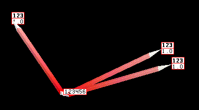
Figure 12-1a, Distributing Coupling and Properties
Kinematic couplings can be used to represent a number of rigid element topologies. Use VIS_SHAPEPOINT to represent a set of couplings arranged as a set of “spokes” connected to a single independent node. Use VIS_SHAPELINE for a series of couplings. Use VIS_SHAPETRI and VIS_SHAPEQUAD for rigid triangular plates and quadrilaterals. Figure 12-1b illustrates a set of 3 kinematic couplings connected to a single independent node with degree of freedom flags.
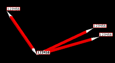
Figure 12-1b, Kinematic Coupling and Properties
Links are designed for representing inextensional couplings which usually involve translational freedoms only. The element topology is usually VIS_SHAPEPOINT or VIS_SHAPELINE with 2 points. Figure 12-1c illustrates a single link with degree of freedom flags.
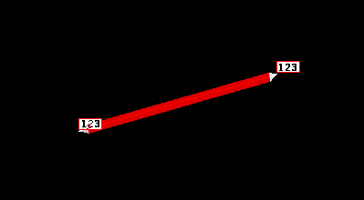
Figure 12-1c, Link and Properties
Multipoint constraints are drawn assuming that the dependent node is the first node. Therefore the topology should be set to VIS_SHAPEPOINT. Figure 12-1d illustrates a multipoint constraint involving 4 nodes.
Figure 12-1d, Multipoint Constraint and Properties
If a rigid element is drawn as a bitmap or pixmap then the basic representation is the same for all special types. The pixmap representation is shown in Figure 12-1e.
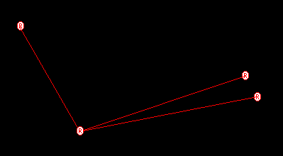
Figure 12-1e, Rigid Element as a Pixmap
A kinematic coupling with a topology set to VIS_SHAPEQUAD drawn in the basic representation is illustrated in Figure 12-1f. The element is filled with 50 percent transparency.
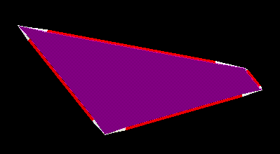
Figure 12-1f, Basic Quadrilateral Kinematic Coupling
13.3. Function Descriptions
The currently available RigidElem functions are described in detail in this section.
-
vis_RigidElem *vis_RigidElemBegin(void)
create an instance of an RigidElem object
Create an instance of an RigidElem object. Memory is allocated for the object private data and the pointer to the data is returned. By default all attribute object pointers are NULL.
Destroy an instance of a RigidElem object using
void vis_RigidElemEnd (vis_RigidElem *rigidelem)
Return the current value of a RigidElem object error flag using
Vint vis_RigidElemError (vis_RigidElem *rigidelem)
- Returns
The function returns a pointer to the newly created RigidElem object. If the object creation fails, NULL is returned.
-
void vis_RigidElemEnd(vis_RigidElem *p)
destroy an instance of a RigidElem object
-
Vint vis_RigidElemError(vis_RigidElem *p)
return the current value of a RigidElem object error flag
-
void vis_RigidElemSetObject(vis_RigidElem *p, Vint objecttype, Vobject *object)
set pointers to attribute objects
Set a pointer to an attribute object.
- Errors
VIS_ERROR_OBJECTTYPEis generated if an improper objecttype is specified
- Parameters
p – Pointer to RigidElem object.
objecttype – The name of the object type to be set.
x=VIS_COLORMAP           ColorMap object
 =VGL_DRAWFUN            DrawFun object
 =VIS_TRANSMAP           TransMap object
 =VIS_VISCONTEXT         VisContext object
 =VIS_EPROP              EProp object
object – Pointer to the object to be set.
-
void vis_RigidElemSetParami(vis_RigidElem *p, Vint ptype, Vint iparam)
set element display parameters
Set element display parameters. The parameter
RIGIDELEM_PROPenables drawing detailed element properties contained in the EProp attribute object. By defaultRIGIDELEM_PROPis set toVIS_OFF.The parameter
RIGIDELEM_WGTSIZEFLAGenables drawing the sizing of distributing couplings proportionately to the weights at each independent node. Usevis_RigidElemSetParamf()to set the size of unit weight. By defaultRIGIDELEM_WGTSIZEFLAGis set toVIS_OFF.- Errors
VIS_ERROR_ENUMis generated if an improper ptype is specified.
- Parameters
p – Pointer to RigidElem object.
ptype – Type of display parameter to set
x=RIGIDELEM_PROP         Draw detailed properties
 =RIGIDELEM_WGTSIZEFLAG  Weight sizing flag
iparam – Specifies the integer value that ptype will be set to.
x=VIS_OFF                Turn parameter off
 =VIS_ON                 Turn parameter on
-
void vis_RigidElemSetParamf(vis_RigidElem *p, Vint ptype, Vfloat fparam)
set element display parameters
Set element display parameters.
The parameter
RIGIDELEM_WGTSIZEsets the size of a unit weight. Usevis_RigidElemSetParami()to enable weight sizing and detailed element properties. By defaultRIGIDELEM_WGTSIZEis set 1.- Errors
VIS_ERROR_ENUMis generated if an improper ptype is specified.VIS_ERROR_VALUEis generated if an improper fparam is specified.
- Parameters
p – Pointer to RigidElem object.
ptype – Type of display parameter to set
x=RIGIDELEM_WGTSIZE Size of unit weight
fparam – Specifies the value that ptype will be set to.
-
void vis_RigidElemSetTopology(vis_RigidElem *p, Vint shape, Vint maxi)
set element topology
Set element topology. For triangle and quadrilateral shapes maxi = 0 or 2 and Serendipity element node connectivity convention is assumed. See section Computational Cells for a description of element topology conventions.
- Errors
VIS_ERROR_VALUEis generated if an improper maxi is input.VIS_ERROR_ENUMis generated if an improper shape is input.
- Parameters
p – Pointer to RigidElem object.
shape – Element shape parameter
x=VIS_SHAPEPOINT         Point
 =VIS_SHAPELINE          Line
 =VIS_SHAPETRI           Triangle
 =VIS_SHAPEQUAD          Quadrilateral
maxi – The number of points along the i direction. If maxi = 0 then the linear element form of the specified shape is assumed.
-
void vis_RigidElemSetSpec(vis_RigidElem *p, Vint spec)
set special type
Set element special type. By default spec is set to
SYS_RIGID_KINE. The typesSYS_RIGID_DISTandSYS_RIGID_RBE3are drawn identically.- Parameters
p – Pointer to RigidElem object.
spec – Element special type
x=SYS_RIGID_KINE         Kinematic coupling
 =SYS_RIGID_DIST         Distributing coupling
 =SYS_RIGID_JOINT        Joint constraint
 =SYS_RIGID_LINK         Inextensional coupling
 =SYS_RIGID_MPC          Multipoint constraint
 =SYS_RIGID_RBE3         Interpolation constraint
 =SYS_RIGID_SPLINE       Spline constraint
-
void vis_RigidElemCurv(vis_RigidElem *p, Vfloat x[][3])
draw element
Draw a rigid element with node points, x.
- Errors
VIS_ERROR_NULLOBJECTis generated if required attribute objects have not been set usingvis_RigidElemSetObject().
- Parameters
p – Pointer to RigidElem object.
x – Array of node locations defining element connections.
13.4. Mass Elements - MassElem
Use the MassElem module to draw various types of mass elements. The basic element representation is primarily dependent upon the element special type. The special types include scalar mass, lumped mass, and mass matrix. The detailed element properties draw icons for translational and/or rotational mass, mass offset and degree of freedom attachments.
The functions associated with a MassElem object are the following.
Begin and end an instance of an object, return object error flag
vis_MassElemBegin()- create an instance of a MassElem objectvis_MassElemEnd()- destroy an instance of a MassElem objectvis_MassElemError()- return MassElem object error flag
Set, manipulate and query results
vis_MassElemCurv()- draw elementvis_MassElemSetLocalSystem()- set local coordinate system conventionvis_MassElemSetObject()- set pointers to attribute objectsvis_MassElemSetParami()- set element display parametersvis_MassElemSetSpec()- set special typevis_MassElemSetTopology()- set element topology
Instance a MassElem object using vis_MassElemBegin().
The basic element representation is dependent upon the element topology
set using vis_MassElemSetTopology(), the element special type set using
vis_MassElemSetSpec() and the element local system set using
vis_MassElemSetLocalSystem(). The element is drawn using
vis_MassElemCurv().
A mass element topology is restricted to VIS_SHAPEPOINT with one or
two nodes and VIS_SHAPELINE with two nodes only.
Detailed element properties may be drawn by registering an
EProp
attribute object using vis_MassElemSetObject()
and enabling property drawing using vis_MassElemSetParami().
In this case the element icons are drawn depending upon the existence of
translational and/or rotational mass. In addition any offset of the mass
from the attachment node is drawn. and any defined degree of freedom
attachments are labeled.
13.5. Attribute Objects
A MassElem object uses DrawFun, VisContext,
ColorMap and EProp
objects to define attributes to generate an element representation. The
DrawFun, VisContext and ColorMap
objects are required. The EProp
object is required only if detailed property drawing is enabled using
vis_MassElemSetParami().
A MassElem object uses the following VisContext
components.
AColor |
Color of degree of freedom flags raster text |
BitmapSize |
Bitmap expansion factor |
ElemAxes |
Element local coordinate system axes flags |
ElemRep |
Element representation. VIS_ELEMREP_SOLID, VIS_ELEMREP_SEMI |
Color |
Color of line connections and mass icon. |
Fill |
Fill flag. |
LineWidth |
Line width of mass offset. |
LineStyle |
Line style of mass offset. |
MinorColor |
Color of rotational mass and mass offset. |
Ratio |
The length of the vector head relative to the total length of the |
Refinement |
Level of refinement |
Shade |
Flag to apply light source shading |
Size |
Size of mass icons and length of coordinate system axes. |
Flags |
The flag VIS_DOFBACK enables drawing a background on behind the |
XColor |
Color of coordinate system x axes |
YColor |
Color of coordinate system y axes |
ZColor |
Color of coordinate system z axes |
The mass element representation is generally dependent upon the element special type and its properties. Figures 12-2a through 12-2c illustrate the detailed representation using ElemRep set to VIS_ELEMREP_SOLID and a topology set to VIS_SHAPEPOINT for each of the 3 element special types.
The detailed mass element properties consist of the existence of translational and/or rotational mass, mass offset and any defined degree of freedom attachments. The degree of freedom attachments are drawn using raster text at each applicable node. The properties drawn depend upon the element special type.
Scalar mass properties include the degree of freedom attachments only. Figure 12-2a illustrates a scalar mass with these properties. A BitmapSize of 2 is used. An element local system is not applicable.
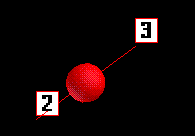
Figure 12-2a, Scalar Mass and Properties
Lumped mass properties include translational and/or rotational mass and mass offset. Figure 12-2b illustrates a lumped mass with these properties. An element local system is drawn.
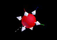
Figure 12-2b, Lumped Mass and Properties
The mass matrix representation does not depend on the element properties. Figure 12-2c illustrates a mass matrix. An element local system is drawn.
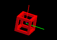
Figure 12-2c, Mass Matrix
13.6. Function Descriptions
The currently available MassElem functions are described in detail in this section.
-
vis_MassElem *vis_MassElemBegin(void)
create an instance of an MassElem object
Create an instance of a MassElem object. Memory is allocated for the object private data and the pointer to the data is returned. By default all attribute object pointers are NULL.
Destroy an instance of a MassElem object using
void vis_MassElemEnd (vis_MassElem *masselem)
Return the current value of a MassElem object error flag using
Vint vis_MassElemError (vis_MassElem *masselem)
- Returns
The function returns a pointer to the newly created MassElem object. If the object creation fails, NULL is returned.
-
void vis_MassElemEnd(vis_MassElem *p)
destroy an instance of a MassElem object
-
Vint vis_MassElemError(vis_MassElem *p)
return the current value of a MassElem object error flag
-
void vis_MassElemSetObject(vis_MassElem *p, Vint objecttype, Vobject *object)
set pointers to attribute objects
Set a pointer to an attribute object.
- Errors
VIS_ERROR_OBJECTTYPEis generated if an improper objecttype is specified.
- Parameters
p – Pointer to MassElem object.
objecttype – The name of the object type to be set.
x=VIS_COLORMAP           ColorMap object
 =VGL_DRAWFUN            DrawFun object
 =VIS_VISCONTEXT         VisContext object
 =VIS_EPROP              EProp object
object – Pointer to the object to be set.
-
void vis_MassElemSetTopology(vis_MassElem *p, Vint shape, Vint maxi)
set element topology
Set element topology. For line shapes, maxi must equal 0 or 2. See section Computational Cells for a description of element topology conventions.
- Errors
VIS_ERROR_VALUEis generated if an improper maxi is input.VIS_ERROR_ENUMis generated if an improper shape is input.
- Parameters
p – Pointer to MassElem object.
shape – Element shape parameter
x=VIS_SHAPEPOINT         Point
 =VIS_SHAPELINE          Line
maxi – The number of points along the i direction. If maxi = 0 then the linear element form of the specified shape is assumed.
-
void vis_MassElemSetLocalSystem(vis_MassElem *p, Vint type, Vfloat vec[], Vfloat angle)
set local coordinate system convention
Specify the convention to be used to construct the orientation of the mass element. Note that if the element consists of a single node or two coincident nodes then the local system must be
SYS_ELEMSYS_GLOBALorSYS_ELEMSYS_ROTANG. By default type isSYS_ELEMSYS_GLOBALand angle is zero.- Errors
VIS_ERROR_ENUMis generated if an improper type is input.
- Parameters
p – Pointer to MassElem object.
type – Local system convention
x=SYS_ELEMSYS_STANDARD   Standard orientation
 =SYS_ELEMSYS_POSITION   Orient to position vector
 =SYS_ELEMSYS_GLOBAL     Global axis
 =SYS_ELEMSYS_GLOBALPROJECT  Orient to global axis projection
 =SYS_ELEMSYS_GLOBALCLOSEST  Orient to closest global axis
 =SYS_ELEMSYS_VECTOR     Orient to direction vector
 =SYS_ELEMSYS_ROTANG     Orient to rotation angle vector
 =SYS_ELEMSYS_BISECTOR   Orient to element bisector
vec – Orientation position, direction or normal vector(s)
angle – Angle to rotate element y’,z’ axes about the element x’ axis in degrees.
-
void vis_MassElemSetParami(vis_MassElem *p, Vint ptype, Vint iparam)
set element display parameters
Set element display parameters.
The parameter
MASSELEM_PROPenables drawing detailed element properties contained in the EProp attribute object. By defaultMASSELEM_PROPis set toVIS_OFF.The parameter
MASSELEM_CHECKERenables drawing a mass matrix element as a checkered cube. If disabled, a mass matrix is drawn as an “edged” cube. By defaultMASSELEM_CHECKERis set toVIS_OFF.- Errors
VIS_ERROR_ENUMis generated if an improper ptype is specified.
- Parameters
p – Pointer to MassElem object.
ptype – Type of display parameter to set
x=MASSELEM_PROP          Draw detailed properties
 =MASSELEM_CHECKER       Draw checkered cube mass matrix
iparam – Specifies the integer value that ptype will be set to.
x=VIS_OFF                Turn parameter off
 =VIS_ON                 Turn parameter on
-
void vis_MassElemSetSpec(vis_MassElem *p, Vint spec)
set special type
Set element special type. By default type is set to
SYS_MASS_SCALAR.- Parameters
p – Pointer to MassElem object.
spec – Element special type
x=SYS_MASS_SCALAR        Scalar mass
 =SYS_MASS_LUMP          Lumped mass
 =SYS_MASS_MATRIX        Mass matrix
-
void vis_MassElemCurv(vis_MassElem *p, Vfloat x[][3])
draw element
Draw a mass element with node points, x.
- Errors
VIS_ERROR_NULLOBJECTis generated if required attribute objects have not been set usingvis_MassElemSetObject().
- Parameters
p – Pointer to MassElem object.
x – Array of node locations defining element connections.
13.7. Spring and Dashpot Elements - DiscElem
Use the DiscElem module to draw various types of spring and dashpot elements. The basic element representation is primarily dependent upon the element special type. The special types include scalar spring and dashpot, link, spot weld, and bushing. The detailed element properties draw icons for translational and/or rotational stiffness, damping and degree of freedom attachments.
The functions associated with a DiscElem object are the following.
Begin and end an instance of an object, return object error flag
vis_DiscElemBegin()- create an instance of a DiscElem objectvis_DiscElemEnd()- destroy an instance of a DiscElem objectvis_DiscElemError()- return DiscElem object error flag
Set, manipulate and query results
vis_DiscElemCurv()- draw elementvis_DiscElemSetLocalSystem()- set local coordinate system conventionvis_DiscElemSetObject()- set pointers to attribute objectsvis_DiscElemSetParami()- set element display parametersvis_DiscElemSetSpec()- set special typevis_DiscElemSetTopology()- set element topology
Instance a DiscElem object using vis_DiscElemBegin().
The basic element representation is dependent upon the element topology
set using vis_DiscElemSetTopology(), the element special type set using
vis_DiscElemSetSpec() and the element local system set using
vis_DiscElemSetLocalSystem(). The element is drawn using
vis_DiscElemCurv().
A spring element topology is restricted to VIS_SHAPEPOINT with any
number of nodes and VIS_SHAPELINE with two nodes only.
Detailed element properties may be drawn by registering an
EProp attribute object using vis_DiscElemSetObject()
and enabling property drawing using vis_DiscElemSetParami().
In this case the element icons are drawn depending upon the existence of
translational and/or rotational stiffness and damping. Any defined
degree of freedom attachments are labeled.
13.8. Attribute Objects
A DiscElem object uses DrawFun, VisContext,
ColorMap and EProp
objects to define attributes to generate an element representation. The
DrawFun, VisContext and ColorMap
objects are required. The EProp
object is required only if detailed property drawing is enabled using
vis_DiscElemSetParami().
A DiscElem object uses the following VisContext
components.
AColor |
Color of degree of freedom flags raster text |
BitmapSize |
Bitmap expansion factor |
ElemAxes |
Element local coordinate system axes flags |
ElemRep |
Element representation. VIS_ELEMREP_SOLID, VIS_ELEMREP_SEMI |
Color |
Color of line connections and spring icon. |
Fill |
Fill flag. |
MinorColor |
Color of ground icon |
Refinement |
Level of refinement |
Shade |
Flag to apply light source shading |
Size |
Size of spring icons and length of coordinate system axes. |
XColor |
Color of coordinate system x axes |
YColor |
Color of coordinate system y axes |
ZColor |
Color of coordinate system z axes |
The spring element representation is dependent upon the element topology, special type and its properties. Figures 12-3a through 12-3d illustrate the detailed representation using ElemRep set to VIS_ELEMREP_SOLID and a topology set to VIS_SHAPEPOINT for each of the 4 element special types.
Scalar spring properties include the degree of freedom attachments only. Figure 12-3a illustrates a scalar spring with these properties. A BitmapSize of 2 is used. An element local system is not applicable.
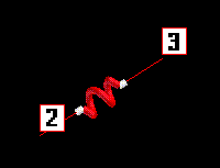
Figure 12-3a, Scalar Spring and Properties
The link spring and dashpot properties include the existence of stiffness and/or damping coefficients. Figure 12-3b illustrates a scalar spring and and dashpot. An element local system is drawn
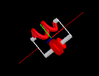
Figure 12-3b, Link Spring and Dashpot
The weld spring properties include the diameter. The icon is a cylinder of the specified diameter. Figure 12-3c illustrates a weld spring. An element local system is drawn
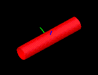
Figure 12-3c, Weld Spring
The bush spring properties include spring stiffnesses in each of 3 translational and 3 rotational directions. Figure 12-3d illustrates a bush spring. An element local system is drawn
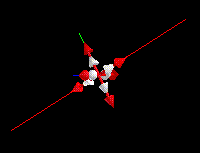
Figure 12-3d, Bush Spring
13.9. Function Descriptions
The currently available DiscElem functions are described in detail in this section.
-
vis_DiscElem *vis_DiscElemBegin(void)
create an instance of an DiscElem object
Create an instance of a DiscElem object. Memory is allocated for the object private data and the pointer to the data is returned. By default all attribute object pointers are NULL.
Destroy an instance of a DiscElem object using
void vis_DiscElemEnd (vis_DiscElem *discelem)
Return the current value of a DiscElem object error flag using
Vint vis_DiscElemError (vis_DiscElem *discelem)
- Returns
The function returns a pointer to the newly created DiscElem object. If the object creation fails, NULL is returned.
-
void vis_DiscElemEnd(vis_DiscElem *p)
destroy an instance of a DiscElem object
-
Vint vis_DiscElemError(vis_DiscElem *p)
return the current value of a DiscElem object error flag
-
void vis_DiscElemSetObject(vis_DiscElem *p, Vint objecttype, Vobject *object)
set pointers to attribute objects
Set a pointer to an attribute object.
- Errors
VIS_ERROR_OBJECTTYPEis generated if an improper objecttype is specified.
- Parameters
p – Pointer to DiscElem object.
objecttype – The name of the object type to be set.
x=VIS_COLORMAP           ColorMap object
 =VGL_DRAWFUN            DrawFun object
 =VIS_VISCONTEXT         VisContext object
 =VIS_EPROP              EProp object
object – Pointer to the object to be set.
-
void vis_DiscElemSetTopology(vis_DiscElem *p, Vint shape, Vint maxi)
set element topology
Set element topology. For line shapes, maxi must equal 0 or 2. See section Computational Cells for a description of element topology conventions.
- Errors
VIS_ERROR_VALUEis generated if an improper maxi is input.VIS_ERROR_ENUMis generated if an improper shape is input.
- Parameters
p – Pointer to DiscElem object.
shape – Element shape parameter
maxi – The number of points along the i direction. If maxi = 0 then the linear element form of the specified shape is assumed.
-
void vis_DiscElemSetLocalSystem(vis_DiscElem *p, Vint type, Vfloat vec[], Vfloat angle)
set local coordinate system convention
Specify the convention to be used to construct the orientation of the spring element. Note that if the element consists of a single node or two coincident nodes then the local system must be
SYS_ELEMSYS_GLOBALorSYS_ELEMSYS_ROTANG. By default type isSYS_ELEMSYS_GLOBALCLOSESTand angle is zero.- Errors
VIS_ERROR_ENUMis generated if an improper type is input.
- Parameters
p – Pointer to DiscElem object.
type – Local system convention
x=SYS_ELEMSYS_STANDARD   Standard orientation
 =SYS_ELEMSYS_POSITION   Orient to position vector
 =SYS_ELEMSYS_GLOBAL     Global axis
 =SYS_ELEMSYS_GLOBALPROJECT  Orient to global axis projection
 =SYS_ELEMSYS_GLOBALCLOSEST  Orient to closest global axis
 =SYS_ELEMSYS_VECTOR     Orient to direction vector
 =SYS_ELEMSYS_ROTANG     Orient to rotation angle vector
 =SYS_ELEMSYS_BISECTOR   Orient to element bisector
vec – Orientation position, direction or normal vector(s)
angle – Angle to rotate element y’,z’ axes about the element x’ axis in degrees.
-
void vis_DiscElemSetParami(vis_DiscElem *p, Vint ptype, Vint iparam)
set element display parameters
Set element display parameters. The parameter
DISCELEM_PROPenables drawing detailed element properties contained in the EProp attribute object. By defaultDISCELEM_PROPis set toVIS_OFF.- Errors
VIS_ERROR_ENUMis generated if an improper ptype is specified.
- Parameters
p – Pointer to DiscElem object.
ptype – Type of display parameter to set
x=DISCELEM_PROP Draw detailed properties
iparam – Specifies the integer value that ptype will be set to.
x=VIS_OFF                Turn parameter off
 =VIS_ON                 Turn parameter on
-
void vis_DiscElemSetSpec(vis_DiscElem *p, Vint spec)
set special type
Set element special type. By default spec is set to
SYS_SPRINGDASHPOT_SCALAR.- Parameters
p – Pointer to DiscElem object.
spec – Element special type
x=SYS_SPRINGDASHPOT_SCALAR Scalar springdashpot
 =SYS_SPRINGDASHPOT_LINK   Link
 =SYS_SPRINGDASHPOT_WELD   Spot weld
 =SYS_SPRINGDASHPOT_BUSH   Bushing
-
void vis_DiscElemCurv(vis_DiscElem *p, Vfloat x[][3])
draw element
Draw a spring element with node points, x.
- Errors
VIS_ERROR_NULLOBJECTis generated if required attribute objects have not been set usingvis_DiscElemSetObject().
- Parameters
p – Pointer to DiscElem object.
x – Array of node locations defining element connections.
13.10. Gap Elements - GapElem
Use the GapElem module to draw uniaxial gap elements. There are currently no special types for gap elements. The detailed element properties include representing the initial gap.
The functions associated with a GapElem object are the following.
Begin and end an instance of an object, return object error flag
vis_GapElemBegin()- create an instance of a GapElem objectvis_GapElemEnd()- destroy an instance of a GapElem objectvis_GapElemError()- return GapElem object error flag
Set, manipulate and query results
vis_GapElemCurv()- draw elementvis_GapElemSetLocalSystem()- set local coordinate system conventionvis_GapElemSetObject()- set pointers to attribute objectsvis_GapElemSetParami()- set element display parametersvis_GapElemSetTopology()- set element topology
Instance a GapElem object using vis_GapElemBegin().
The basic element representation is dependent upon the element topology
set using vis_GapElemSetTopology() and the element local system set using
vis_GapElemSetLocalSystem().
The element is drawn using vis_GapElemCurv().
A gap element topology is restricted to VIS_SHAPEPOINT with one or
two nodes and VIS_SHAPELINE with two nodes only. A gap element with
a single node is assumed to be a node to ground gap, a special ground
icon is included in the gap element representation.
Detailed element properties may be drawn by registering an
EProp attribute object using vis_GapElemSetObject()
and enabling property drawing using vis_GapElemSetParami().
In this case the gap element initial gap is represented exactly in the
spacing of the gap element icons.
13.11. Attribute Objects
A GapElem object uses DrawFun, VisContext,
ColorMap and EProp
objects to define attributes to generate an element representation. The
DrawFun, VisContext and ColorMap
objects are required. The EProp
object is required only if detailed property drawing is enabled using
vis_GapElemSetParami().
A GapElem object uses the following VisContext
components.
AColor |
Color of degree of freedom flags raster text |
BitmapSize |
Bitmap expansion factor |
ElemAxes |
Element local coordinate system axes flags |
ElemRep |
Element representation. VIS_ELEMREP_SOLID, VIS_ELEMREP_SEMI |
Color |
Color of line connections and gap icon. |
Fill |
Fill flag. |
MinorColor |
Color of ground icon |
Refinement |
Level of refinement |
Shade |
Flag to apply light source shading |
Size |
Size of gap icons and length of coordinate system axes. |
XColor |
Color of coordinate system x axes |
YColor |
Color of coordinate system y axes |
ZColor |
Color of coordinate system z axes |
The gap element representation is dependent upon the element topology and its properties. Figures 12-4a and 12-4b illustrate the point to point gap and the point to ground gap using ElemRep set to VIS_ELEMREP_SOLID. The detailed gap element properties consist of the initial gap.
The point to point gap orients the gap icon along the element x’ coordinate system which may, in general, not necessarily be aligned between the node connections. Figure 12-4a illustrates a point to point gap. An element local system is drawn.
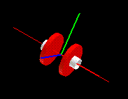
Figure 12-4a, Point to Point Gap
The point to ground gap orients the gap icon along the element x’ coordinate system. Figure 12-4b illustrates a point to ground gap. An element local system is drawn.
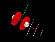
Figure 12-4b, Point to Ground Gap
13.12. Function Descriptions
The currently available GapElem functions are described in detail in this section.
-
vis_GapElem *vis_GapElemBegin(void)
create an instance of a GapElem object
Create an instance of a GapElem object. Memory is allocated for the object private data and the pointer to the data is returned. By default all attribute object pointers are NULL.
Destroy an instance of a GapElem object using
void vis_GapElemEnd (vis_GapElem *gapelem)
Return the current value of a GapElem object error flag using
Vint vis_GapElemError (vis_GapElem *gapelem)
- Returns
The function returns a pointer to the newly created GapElem object. If the object creation fails, NULL is returned.
-
void vis_GapElemEnd(vis_GapElem *p)
destroy an instance of a GapElem object
-
Vint vis_GapElemError(vis_GapElem *p)
return the current value of a GapElem object error flag
-
void vis_GapElemSetObject(vis_GapElem *p, Vint objecttype, Vobject *object)
set pointers to attribute objects
Set a pointer to an attribute object.
- Errors
VIS_ERROR_OBJECTTYPEis generated if an improper objecttype is specified.
- Parameters
p – Pointer to GapElem object.
objecttype – The name of the object type to be set.
x=VIS_COLORMAP           ColorMap object
 =VGL_DRAWFUN            DrawFun object
 =VIS_VISCONTEXT         VisContext object
 =VIS_EPROP              EProp object
object – Pointer to the object to be set.
-
void vis_GapElemSetTopology(vis_GapElem *p, Vint shape, Vint maxi)
set element topology
Set element topology. For line shapes, maxi must equal 0 or 2. See section Computational Cells for a description of element topology conventions.
- Errors
VIS_ERROR_VALUEis generated if an improper maxi is input.VIS_ERROR_ENUMis generated if an improper shape is input.
- Parameters
p – Pointer to GapElem object.
shape – Element shape parameter
x=VIS_SHAPEPOINT         Point
 =VIS_SHAPELINE          Line
maxi – The number of points along the i direction. If maxi = 0 then the linear element form of the specified shape is assumed.
-
void vis_GapElemSetLocalSystem(vis_GapElem *p, Vint type, Vfloat vec[], Vfloat angle)
set local coordinate system convention
Specify the convention to be used to construct the orientation of the gap element. Note that if the element consists of a single node or two coincident nodes then the local system must be
SYS_ELEMSYS_GLOBALorSYS_ELEMSYS_ROTANG. By default type isSYS_ELEMSYS_GLOBALCLOSESTand angle is zero.- Errors
VIS_ERROR_ENUMis generated if an improper type is input.
- Parameters
p – Pointer to GapElem object.
type – Local system convention
x=SYS_ELEMSYS_STANDARD   Standard orientation
 =SYS_ELEMSYS_POSITION   Orient to position vector
 =SYS_ELEMSYS_GLOBAL     Global axis
 =SYS_ELEMSYS_GLOBALPROJECT  Orient to global axis projection
 =SYS_ELEMSYS_GLOBALCLOSEST  Orient to closest global axis
 =SYS_ELEMSYS_VECTOR     Orient to direction vector
 =SYS_ELEMSYS_ROTANG     Orient to rotation angle vector
 =SYS_ELEMSYS_BISECTOR   Orient to element bisector
vec – Orientation position, direction or normal vector(s)
angle – Angle to rotate element y’,z’ axes about the element x’ axis in degrees.
-
void vis_GapElemSetParami(vis_GapElem *p, Vint ptype, Vint iparam)
set element display parameters
Set element display parameters. The parameter
GAPELEM_PROPenables drawing detailed element properties contained in the EProp attribute object. By defaultGAPELEM_PROPis set toVIS_OFF.- Errors
VIS_ERROR_ENUMis generated if an improper ptype is specified.
- Parameters
p – Pointer to GapElem object.
ptype – Type of display parameter to set
x=GAPELEM_PROP Draw detailed properties
iparam – Specifies the integer value that ptype will be set to.
x=VIS_OFF                Turn parameter off
 =VIS_ON                 Turn parameter on
-
void vis_GapElemCurv(vis_GapElem *p, Vfloat x[][3])
draw element
Draw a gap element with node points, x.
- Errors
VIS_ERROR_NULLOBJECTis generated if required attribute objects have not been set usingvis_GapElemSetObject().
- Parameters
p – Pointer to GapElem object.
x – Array of node locations defining element connections.
